WebUI Configuration
The web-based user interface can be used to configure many common use cases for the CDN Director.
Normally the GUI is accessible from the CDN Manager at an address like
https://cdn-manager/gui/. After navigating to the UI, a login screen will be
presented:
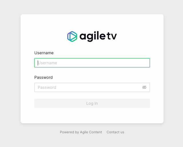
Enter your credentials and log in.
Once logged in, the middle of the screen will present a few sections. Depending on your user’s permissions and licensed features, different options will be made available.
In the general case, two options will be presented:
- CDN Director
- Configuration Panel
At the top right corner is a user menu with an option to log out.
The left-hand side of the page shows a collapsible menu with a few icons:
 filters the menu options
 used to return to the landing page
 link to the
Director Routing rule configuration view
link to the
Director Routing rule configuration view link
to the Director configuration panel view
link
to the Director configuration panel view
CDN Director Routing
This view provides a graphical tree-based model for configuring how the Director should classify and route incoming content requests.
Menu Options
After navigating to the CDN Director Routing page, the left side will show a list of routing rule block types and host group variants. The user can drag and drop items from this list onto the main canvas in order to design a routing solution.
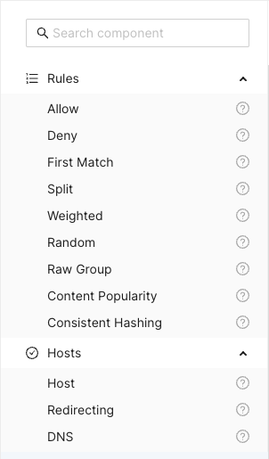
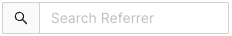
The Search component input field at the top can be used to search and filter
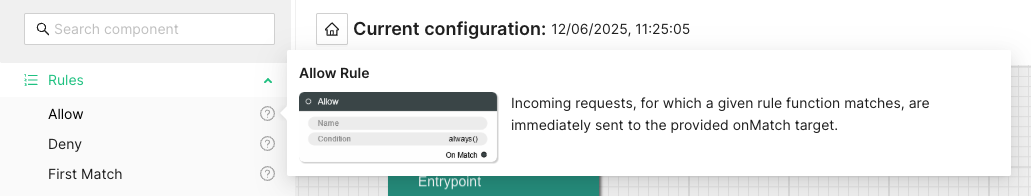
among the available components. Clicking the question mark next to a component
shows a description popup.
Title Bar
Above the main canvas is the title bar. On the left side is the name of the currently selected routing configuration and its creation date:

To the right are a series of buttons, from left to right:

Creates a grouping rectangle on the canvas. Any routing rules placed on this rectangle can be moved around together, making it easier to construct logical units. This is only a visual and practical effect, it doesn’t in any way change the generated configuration.

Opens a popup menu on the right-hand side of the canvas where various configuration options can be changed. A list of CDN Director instances to apply the configuration to can be found and modified here, as well as the general look and feel of the GUI.

Opens a display of the configuration JSON generated from the graphical representation and allows for editing the text directly. Any changes made will automatically be loaded into the graphical representation.

Automatically arranges all the blocks in the canvas, hopefully making it less messy. Routing decision flow begins from the top left and moves rightwards.

Pushes the currently active configuration onto all the configured CDN Director instances. Changes take effect immediately assuming they do not contain any errors and the GUI will display a dialog with the update results.
Saves the configuration to the listed CDN Director targets, with a name provided by the user. Previously saved configurations can be accessed by clicking the house icon next to the configuration title at the middle top of the canvas.
Note that merely saving a configuration does not make it take effect, it is just for making backups or alternative configurations.
To make a configuration take effect, you have to
Publishit.
Saved Configurations
Clicking the  icon in the title bar
navigates to the saved configurations section.
icon in the title bar
navigates to the saved configurations section.
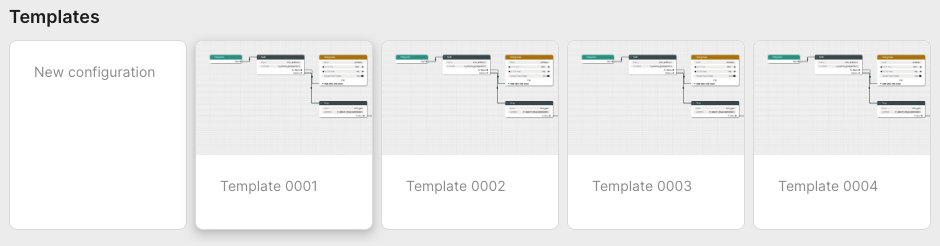
The upper part of this section is a template list allowing the user to either start a new configuration from scratch by selecting “New configuration” or start from a skeleton configuration by selecting one of the available template tiles.
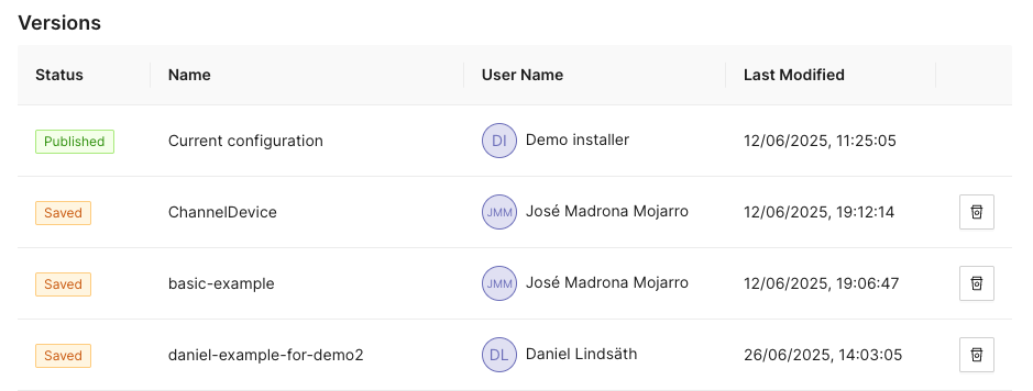
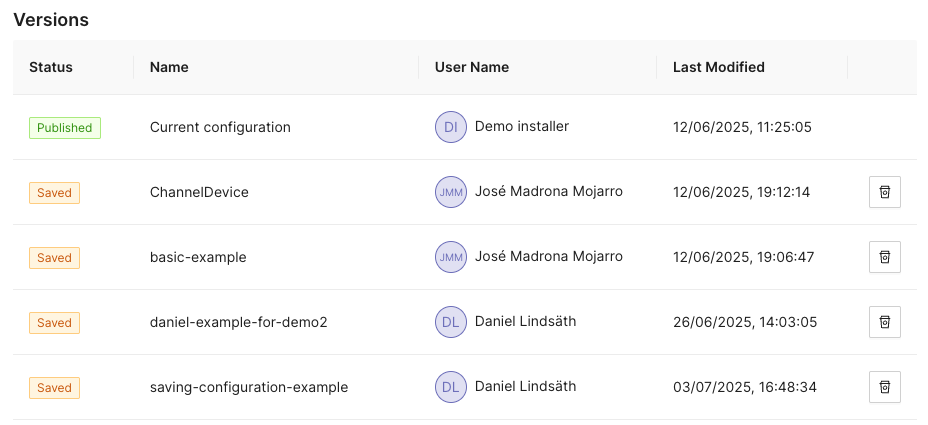
The lower part contains all stored configurations. First in the list is always the currently published configuration, followed by any user-created configurations that have been saved.
Each entry in the list contain information about its name, who created it and when it was last saved. Next to each saved configuration is a trash can button used to delete it.
Configuration Options
Clicking the icon opens a
panel with configuration options and settings on the right-hand side of the
screen. This panel has the two tabs Configurations and Style.
Configuration
The configuration tab allows the user to manage the CDN Director instances that are to be configured by the GUI.
Whenever a user pushes either Publish or Save version, the configuration
will be sent to routers configured in this list.
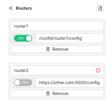
Each entry has a name, an address and a radio button to disable publication to specific instances that are e.g. taken out for maintenance. Turning a Director off won’t affect the current running status of that instance, it will only disable pushing any new configuration to it.
As seen above, the address can be either a full URL with scheme, hostname, port
and path such as http://router1.example.com:5000/config or a relative path
used e.g. to push configurations through an CDN Manager node:
/confd/router1/config.
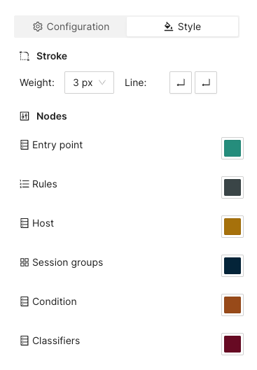
Style Options
This pane contains various settings for the look and feel of the routing configuration view. The user can change line width and stroke type as well as colors associated with different node types.
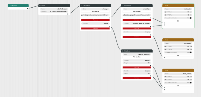
Arrange Button
This button will automatically arrange the routing nodes in the canvas, trying to make the connections easier to follow.
Imagine a user has designed the routing flow organically, placing components anywhere on the screen as their need arose. This can make it difficult to get an overview.
Clicking the Arrange button makes the GUI suggest a more structured
arrangement:
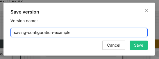
Save Version Button
Sometimes it can be useful to save a copy of a configuration, either because you need to try an entirely different design, or because you want to store a working setup before tweaking it to make sure you can revert to a working state in case anything goes wrong.
Clicking the Save version button opens a dialog box allowing you to pick a
name and save the currently displayed configuration to all the linked CDN
Director instances without activating it.
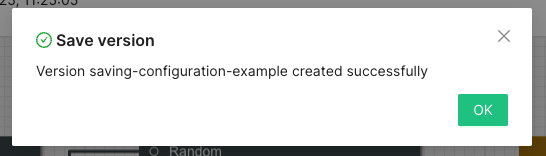
Going back to the saved configurations list, the new entry has appeared:
Publish Button
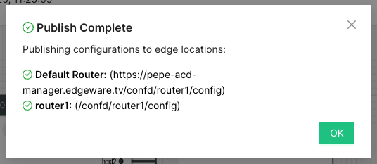
Clicking the Publish button sends the currently displayed configuration to be
sent to all enabled CDN Director instances. If it contains a complete and valid
configuration the Directors will then apply any changes.
A dialog box will display the publish status for each configured Director:
Configuration Panel
The configuration panel view allows for configuring routing-adjacent features, such as blocked/allowed referral addresses, blocked/allowed user agent strings or CDN host capacity values.
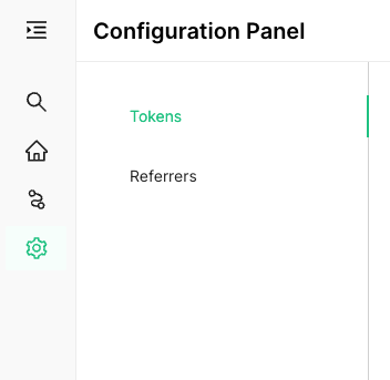
At the moment there are two supported configurations: Blocked tokens and blocked referrers.
Tokens
Selecting Tokens allows the user to observe and edit a list of currently
blocked tokens:
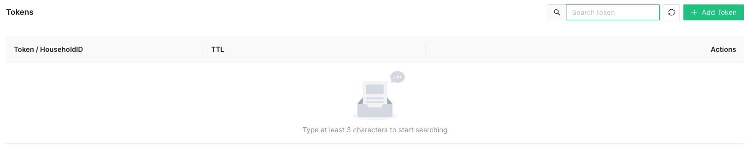
Several actions are available at this point:
Add a new token string to be blocked, along with a corresponding time-to-live (TTL) value in seconds.
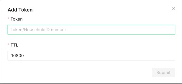
A newly added token will automatically be removed after TTL seconds, to avoid filling up the database with outdated or stale values.
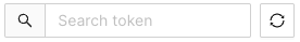
In order to avoid performance hits when there are many tokens, nothing is shown in this list until a search string is entered manually by the operator. This is because a token is added to the list every time a valid token request is made and the database can grow to millions of entries.
At least three characters must be entered for searching to begin. A maximum of 100 results are shown. Write more specific search strings to filter out irrelevant token entries.
Note that token-reuse blocking depends on there being a Routing node, e.g. a
Denyblock, with a suitable condition function that performs the token extraction and blocking.
Referrers
This section allows for blocking specific referrer addresses. Unlike the token list, this table will display entries immediately since it is not anticipated to contain nearly as many entries.
Like with the token list, at most 100 entries are shown at a time. Use the search box to find the relevant referrers if the list is full.
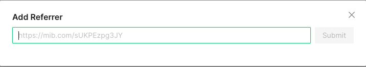
Clicking the button will open a window to add a new referrer string to the block list. Clicking the ‘X’ closes the window without adding a new entry.
The search box filters which already-added referrer strings are displayed in the list. At least three characters must be written for filtering to begin, and regardless of how many matching results there are, only 100 will be displayed in the list so it is recommended to be as specific as necessary when searching.

Clicking the trash can next to a referrer removes it from the list of blocked referrers.
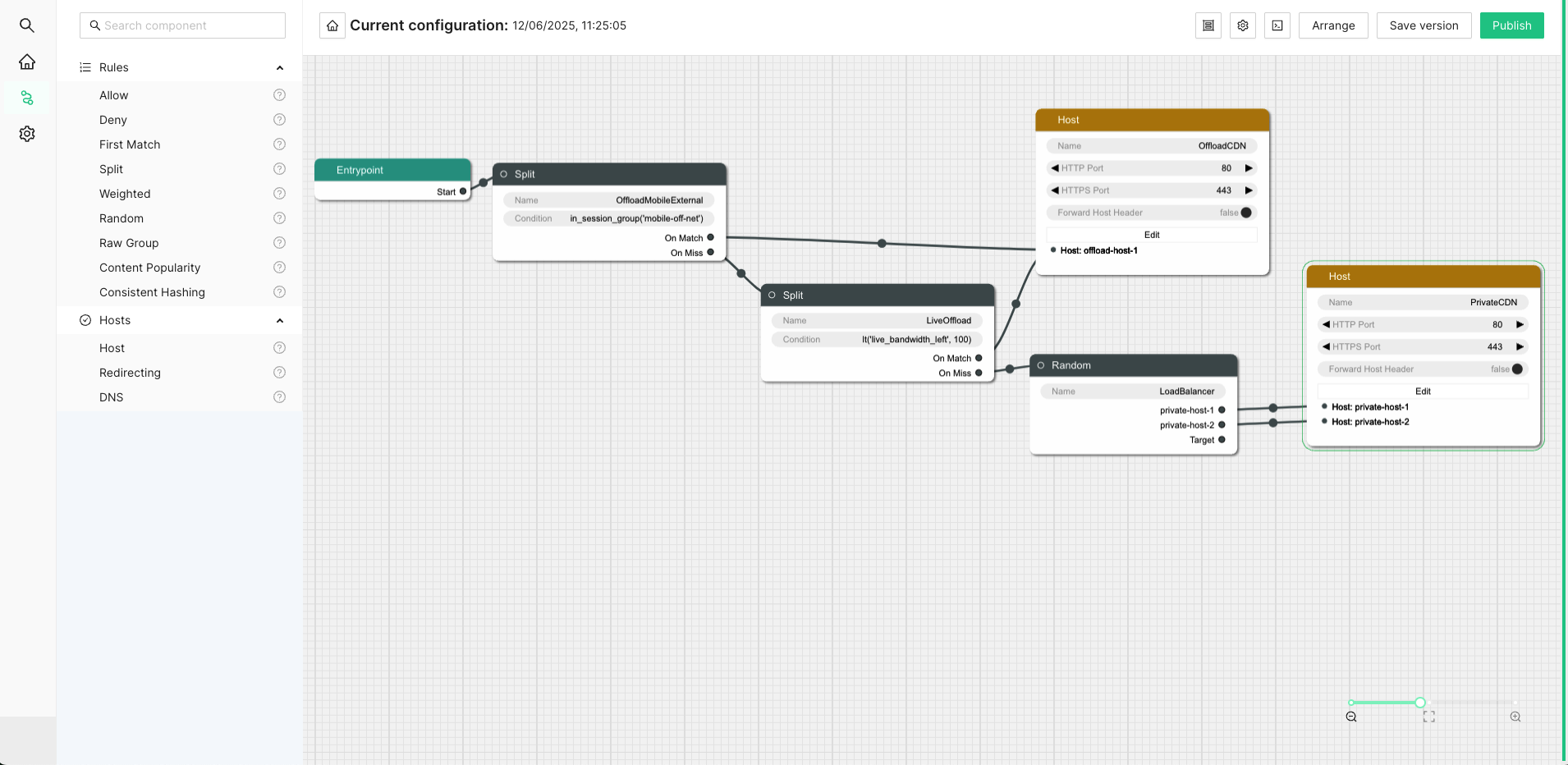
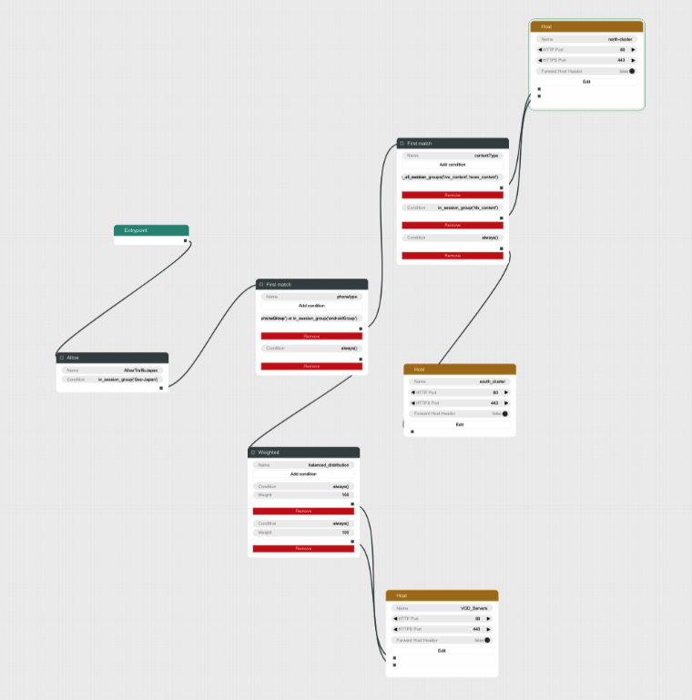
Example Routing Configuration
The following text will describe how to set up a simple routing system that has an internal CDN with two streaming servers and one external CDN.
The internal CDN is meant for serving live TV with low latency as well as VOD traffic provided there is enough capacity left without overloading the servers and affect live traffic latency.
In order to demonstrate the Director’s traffic filtering capability the setup will also send any mobile traffic from outside of Stockholm, Sweden to the external CDN.
Finally, a load balancing node is added to split the remaining incoming requests equally between the two internal hosts.
In summary, the configuration will:
- Route off-net traffic from mobile phones to the external CDN.
- Route Live traffic to the external CDN if the internal CDN is overloaded.
- Route any remaining traffic to the internal CDN.
Step-by-Step Walkthrough
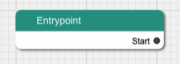
When creating a new configuration the only thing that exists is an Entrypoint
node. This node is used to indicate where the routing engine should begin
traversing the routing tree for a new incoming request.
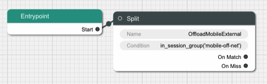
Begin by dragging a Split node onto the canvas and connect it to the
Entrypoint.
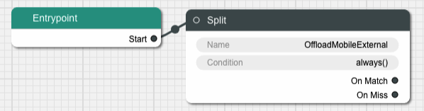
A Split node splits the incoming traffic into two separate streams based on
a condition. The default condition is a function called always() that
evaulates as true for any request. This is not very useful for this example,
replace it by clicking on the Condition input field in the node.
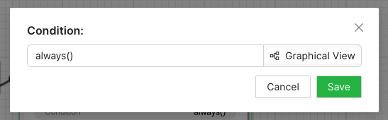
This brings us to a dialog box where we can simply replace the condition with
another string or go to a graphical representation of the condition to help
guide us through the steps to getting the Split node to do what we need.
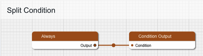
Graphical Condition Builder
Clicking the Graphical View button opens up the graphical representation which
currently shows two condition nodes connected together, one representing the
default condition always() previously mentioned, and one called Condition Output which is a target placeholder for the end result of the entire graph.
Output from one condition node is connected to the input of another node until
the entire chain ends up with the Condition Output node.
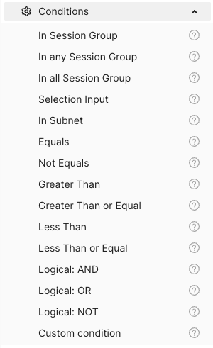
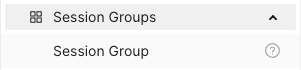
On the left-hand side is a menu with the items Session Groups, Conditions
and Classifiers. The Conditions section contains different condition
components whose outputs can be connected to either other condition nodes or
the Condition Output.
Delete the Always node and replace it with one from the Conditions menu,
specifically In Session Group, and connect its output to Condition Output.
The new condition node takes a Session Group as its input. Drag one of those
from the menu onto the canvas and connect its output to the input labeled
“Session Group”. Give the Session Group node the name “mobile-off-net” since
it is going to contain requests from mobile units outside of the main network.
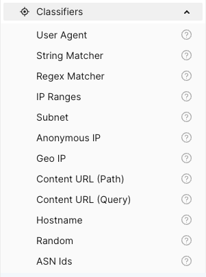
The Session Group takes a number of classifiers as inputs. Open the
Classifiers section of the menu and drag a Geo IP and a User Agent node
onto the canvas and connect their outputs to the Session Group. Note that
when one classifier is connected, the connection label is updated with its name
and a new empty connection slot is added.
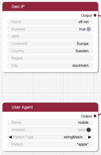
Fill in the two classifier nodes with appropriate values:
Give the Geo IP node the name “off-net”, set Continent to “Europe”,
Country to “Sweden” and City to “Stockholm”. Finally, change the Inverted
toggle to true since we want this condition to match any traffic that comes
from anywhere but Stockholm.
The User Agent node is meant to match mobile devices, but for simplicity’s
sake this classifier is limited to Apple devices for this example. Set the name
to “mobile”, make sure Pattern Type is “stringMatch” and set the pattern to
“apple”. The asterisks will match against any strings at the beginning and end
of the user agent string, and “apple” is case insensitive.
The resulting graph should look like this:
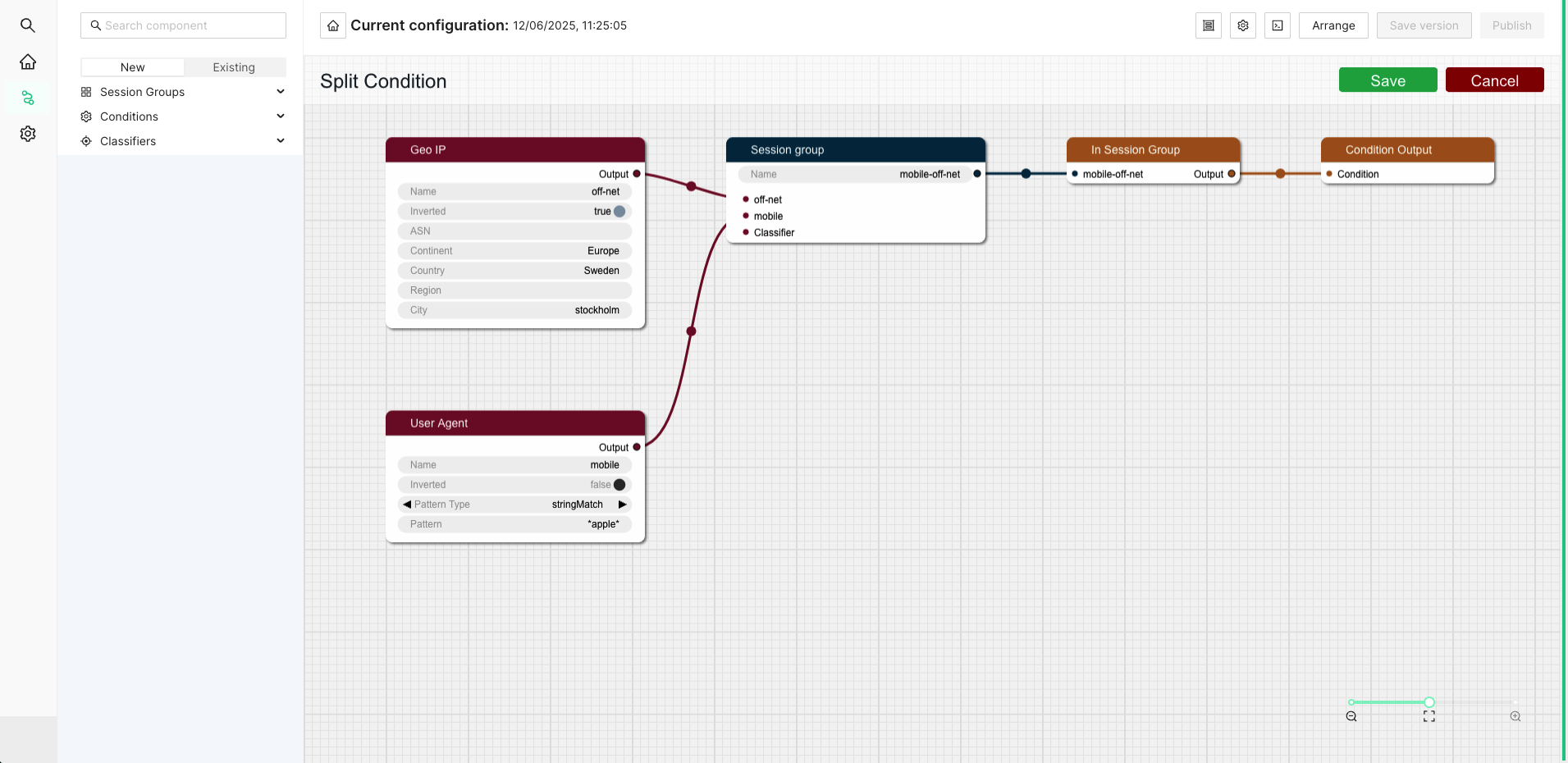
Click Save to return to the routing tree configuration view. Note that
"always()" has been replaced with "in_session_group('mobile-off-net')".
It is time to add a node for the external CDN. Open up the Hosts section in
the left-hand side menu if it is closed. Then drag a Host node onto the
canvas and name it “OffloadCDN”.
This creates a host group which contains hosts which belong together and share common settings such as ports.
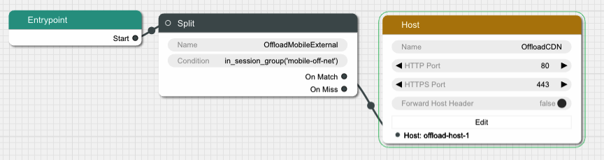
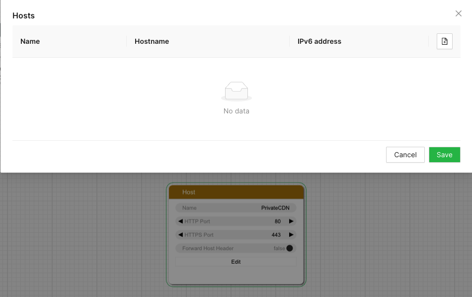
Click the Edit button to open a dialog where the actual hosts can be added to
the host group by clicking the icon with a new document on it. Add a host with
the name “offload-host-1” and address “offload-1.example.com”. The IPv6 address field can be left empty.
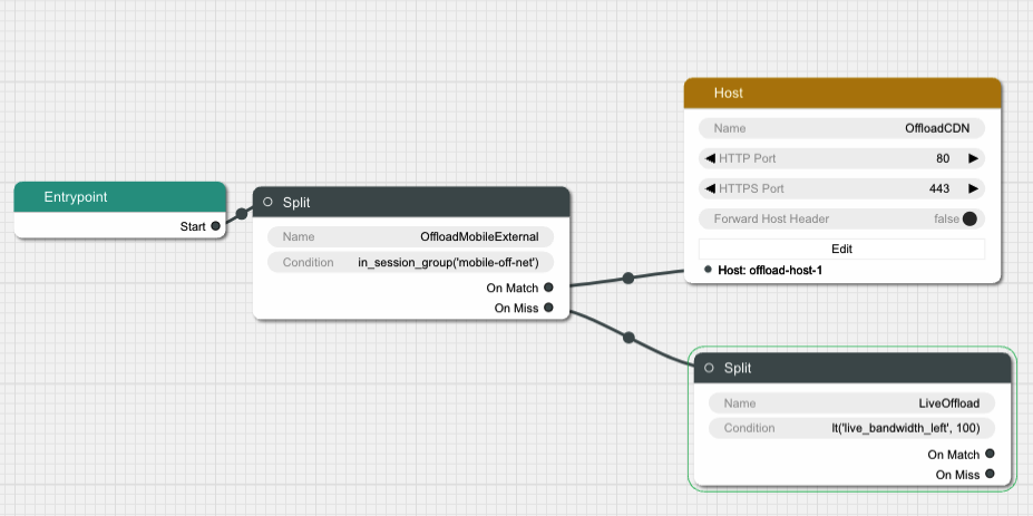
Click Save to return to the canvas view and connect the Split node’s
onMatch slot to the newly created host. Now any request that matches the
condition we added to the Split node will be sent to the external host.
The next step is to add an offload in case the internal CDN is overloaded. Add
another Split node, call it “LiveOffload” and connect it to the previous
Split node’s onMiss slot. We will use a Selection Input
value named "live_bandwidth_left" to determine whether or not the internal CDN
is overloaded.
Click the Condition field and bring up the graphical view. Remove the
default Always node and replace it with a Less Than node. Set its Selection Input string to “live_bandwidth_left” and the Value to 100 in order to send
traffic to the offload CDN whenever the internal CDN reports less than 100
capacity left.
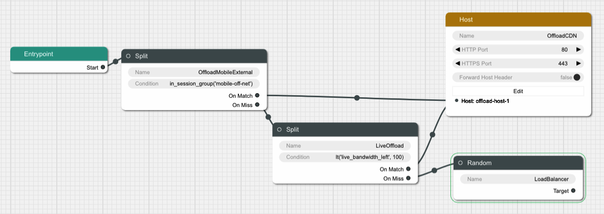
Save the condition and connect the Split node’s onMatch output to the
“offload-host-1” Host.
In order to balance the incoming Live traffic between the two internal CDN nodes
we create a Random node, which simply splits the traffic equally among its
targets.
Finally we create another Host node and give it two hosts called
“private-host-1” and “private-host-2”. Connect the Random node to the two
hosts and the routing configuration is finished.